How to use Audio DSP on Antenna Analyzer (Features included after CEC V0.5)
Audio DSP is a function that filters the sound coming from the transceiver into a desired range.
You do not need any hardware changes to use this feature. Just prepare your headphones. If you want to make a little bit better, you can add a very small $ 1 speaker to your board.
I am preparing to distribute the test firmware (V0.52). Please wait 1 ~ 2 days.
1.Required Hardware
EU1KY AA and Headphone.
The STM32F746 board has two sound inputs. However, Mic Jack is already using the EU1KY RF board.
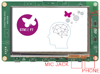
Another sound input method of the STM32F746 is two microphones mounted on the board.
I use only one of the two microphones. (Right)
Put AA near the transceiver speaker and plug your headphone into the phone jack and you're all set.
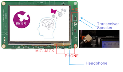
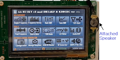
Or you can install a small speaker as shown below.
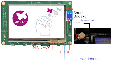
You could easily get a small speaker around you. It can be extracted from malfunctioning headphone, earphone, mobile phone.
The speakers I used are below.
https://www.aliexpress.com/item/2pcs-1W8ohm-MP3-MP4-small-horn-Ramos-v2-0-10-15-oval-speaker-W10/32779312057.html?spm
2.How to use
Below is a picture of my development board. I put a very small speaker on Mic for testing.
On the main screen, touch 'Audo DSP' button.
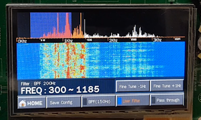
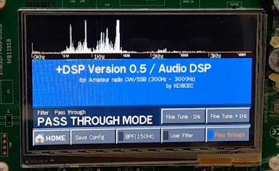
If you turn on your transceiver, you will probably see fft spectrum and waterfall graphs as shown below.
In the first run, it operates in 'Pass Through' mode.
May be too loud, so make sure the volume of the transceiver is very small in 'Pass through' mode.
Touch the desired filter button.
If you are filtering a fairly narrow area, please select BPF.
BPF supports 50Hz, 100Hz and 150Hz filtering.
Continue to touch the BPF button to change the filtering bandwidth.
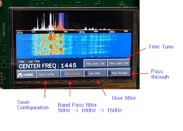
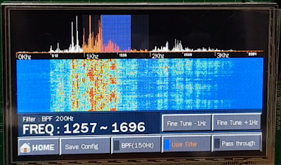
Touch the red squares (B) below to move the center frequency.
The yellow squares(A) is the area to adjust the bandwidth in User Filter mode.
Move the center frequency to the area you want to hear.
If you hear a small noise when moving to the area you want to hear, increase the volume of the transceiver.
Since most of the other areas are removed, if you raise the volume, you will hear what you want to qso. Volume control is important.
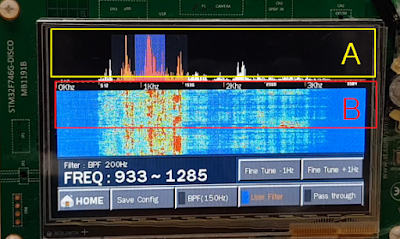
If you have selected User Filter, you can select the range you want to hear by dragging the L and R areas below.
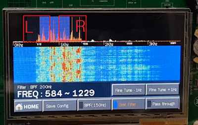
Since the center frequency is maintained even if you touch the BPF and the User filter alternately, it can be used alternately according to the communication status.
3.Test Video
Please refer to the video below for an example of use.
Thank you for reading
Ian KD8CEC
Hello Ian,
ReplyDeleteNext version will be receiver and final version will be all band transceiver? :-)
Mirek
DeleteIt is wonderful. However, it seems to be difficult to structure the circuit.
I am not an active ham. So I just use the antenna analyzer once or twice a month.
Most of the time, the antenna analyzer is left on the desk.
So I'm adding a few minor features.
Ian KD8CEC
Can't we use the Audio In Jack, to which I and V outputs of the RF board of EU1KY VNA is connected ? We can directly connect the Headphone out of our Rig to the VNA and get the output from the Speaker out ? Using Microphone would pick up sound from the Shack.
ReplyDeleteVU3ECN
DeleteWe can not use Audio IN Jack. So we have to use a microphone attached to the board. It would be useful to place AA near the speaker of the transceiver.
Or add a small speaker like me.
I'm considering building a HAM tool that will consist of less than $ 60.
This would be a structure consisting only of the STM32F746 board and the SI5351 board.
The Si5351 board will be available for $ 3 on eBay.
I will be porting most of the features I have implemented in AA.
At this time, you can use Audio In Jack of STM32F746 board, so you can connect to the transceiver directly.
But I still considering it.
Ian KD8CEC
Hi Ian,
Deletepardon my lack of knowledge about the Disco Board. Since such a device is better as dedicated one, what you propose would be a welcome thing. Would be looking for update from you. BTW, I have sent the order for the modified PCB for the VNA. I would send you a piece after testing it.
KD8CEC
ReplyDeleteHave a Si5351A board with the
Discovery Board V1.01 Antenna
Analyzer
Want to know if adding a TCXO
with better than 0.5ppm over Temp
might improve FT8 and WSPR
Notice on FT8 unit moves around
in frequency and with WSJT looking
at waterfall see many signals evenly
spaced about Center Carrier on 14.074MHz FT8
Suspect the DC to DC converter
is modulating the Si5351A or other
device to cause spurs
E-mail me at wb6dji_dx(at)icloud(dot)com
Mike
Ian
DeleteThanks in advance for any help
Trying to enhance the
Si5351A add on board for
Improved FT8 operation
Mike
WB6DJI
It is my pleasure to read this wonderful blog of yours. Thank you so much for sharing. Porch Screening Port Charlotte, FL
ReplyDeleteAs you approach the desired listening location, turn up the transceiver's level if you detect any faint sounds. Check truckaccidentattorneycoloradosprings.com
ReplyDeleteUsing Audio DSP on Antenna Analyzer is the best and there are a lot of people searching for the right ideas that bring the results to us. While searching for the roof ventilation installation I saw how the people like to get these ideas to get the desired results.
ReplyDelete