DVPi hardware expansion (PTT, Encoder and etc)
DVPi can be used without any additional hardware. A Raspberry Pi, 3.5" LCD and USB sound card are enough for DMR communication. However, if you want to use DVPi more conveniently, or if you like to make it, I think it is good to configure the hardware as follows.
This hardware is the final version. No hardware will be added to the DVPi anymore.
I would like to introduce the DVPi hardware expansion into several types. You can create DVPi the way you want.
1. Use without any additional hardware
I also recommend this method. The simplest. You can create and use DVPi with just RPI, LCD, USB sound card.
Start DVPi Manager.
Click the 'Settings to use rotary encoder, PTT, and VOX...' button
Then, The DVPi's hardware configuration screen appears.
You should not select anything as shown in the screen below. This is the DVPi default setting screen.
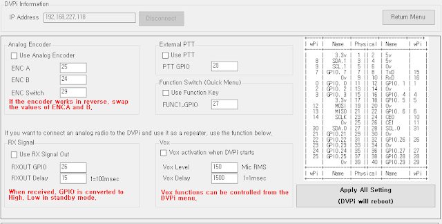
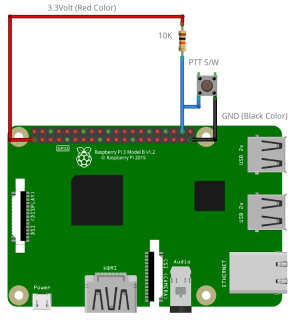
2. PTT extension
To extend the external PTT to DVPi, you only need one 10K resistor and one switch.
Set it as follows. The encoder must be selected even if it is not used.
3. PTT extension (Safty)
To extend the external PTT to DVPi, you only need three 10K resistor and one switch.
This is to attach two pull-up resistors to an encoder that is not in use.
Set it as follows. The encoder must be selected even if it is not used.
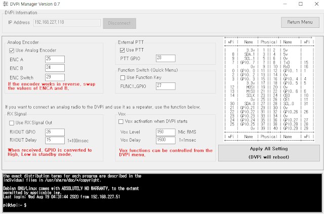
4. Rotrary Encoder and PTT extension
You can use DVPi more conveniently with Rotary Encoder with switch , a switch and 4 10k resistors.
Below is the rotary encoder I use. It is a rotary encoder generally used by Arduino.
I did the following, but if you want to do it easily, you can apply a resistor directly to the rotary encoder.
5. Rotrary Encoder , PTT and Function Key extension
You can add a function key to use the submenu added in Version 0.7 or the Quick Menu function for the visually impaired.
Just like adding a PTT switch, just add one more switch.
Set it as follows.
6. LED extension for Receive Signal indication
I just added the LED function to the above circuit. If you don't need rotary encoder, PTT, function key function, you can use it by connecting only one LED and one resistor.
The LED will light up when voice is received.
Set it as follows. The encoder must be selected even if it is not used.
If you are not using PTT, Rotrary Encoder, Function Key, don't check all checkboxes, just check'Use RX Signal Out'.
The default value of RXOUT Delay is 15, but 3 is recommended when using LEDs. It will look a little active.
7. PC817 extension for Receive Signal indication
Everything is the same as in item 4 above. I just replaced the LED with PC187.
This is for external radio control. I experimented about this 3 times and it was quite satisfactory. I will be posting a separate article on this.
Yes. As you might guess, it is relaying digital and analog using an inexpensive analog radio. Use this only for your personal laboratory use.
Set it as follows. If you connect analog radio to DVPi, it is recommended to set RXOUT Delay value to 5~10.
8. Hardware GPIO numberGPIO numbers are used for all of the above settings. EX: ENC A = 25, ENC B= 24...
I configured the circuit as above, but if you want to use the GPIO for other purposes, you can connect it anywhere.
You can also connect the PTT switch to GPIO 21. In that case, you just need to set the PTT GPIO to 21.
Please refer to the GPIO number below. The GPIO number is based on WiringPi.
9. FM Transmitter Extenction (Just use it for experimental purpose)
Not available on Raspberry Pi 4. only Raspberry PI 1,2,3
FM Transmitting programs existed on the Raspberry Pi from the past.
I changed the RpiNBFM source code to receive UDP data and send it through RF and included it in DVPi as a separate program. (named 'udptonfm') This source code will be posted on git.
This program uses Raspberry pi's DMA, but the program stops functioning frequently due to a conflict with another process. RF transmission stops about once every almost 5 minutes. However, since DVPi periodically restarts the process, the RF signal will be transmitted again after a while.
You should use this feature only for fun and experimental purposes.
You don't need any additional hardware to use this feature. Just change the settings as follows.
Click the Advanced Setting
Checked 'Using FM Transmitter using GPIO 4'
and Set you want Frequency (Khz)
You just need to set the frequency below 250Mhz.
2M, 10M, 11M are all possible.
Sending the radio a little further, If a 1m wire is connected to GPIO 4, radio waves are transmitted over a long distance.
you can alos adding the SMA connector as below.
Again, use FM transmission only for fun and experimental purposes. Periodically, the RF signal will be interrupted, and the DVPi may be down due to a heavy load on the CPU. Also, use it legally in your country's laws.
10.My final DVPi circuit.
Below is my final DVPi circuit.
Again, you don't have to add any hardware to the DVPi. I recommend it too.
It is recommended to keep the CPU temperature of the DVPi below 50 degrees. Just attach a small fan to the DVPi case.
Thank you for reading
Ian KD8CEC


Thank you Ian for a very well detailed explanation, certainly the best Raspberry Pi project for me for sure.
ReplyDeleteJames
It would be quite useful to have a rotary encoder.
DeleteIan
Ian, what sort of microphone would you recommend ?
ReplyDeletethank you
James
You can use anything. You can simply connect the capacitor mic.
DeleteHowever, it is recommended to use a handy microphone equipped with a microphone and PTT.
One thing to note is that the Raspberry Pi's Mic Gain is quite large. You must lower Mic Gain.
Ian KD8CEC
Thank you Ian.
DeleteHi Ian,
ReplyDeleteQuestion: typing it TG 9990 Parrot did not work for me is it implamented ?
or as usual am I doing some thing wrong, ... Just trying to test mic gain..
James
In Keypad Windows press 9990# then OK
DeleteEven with the same sound card, you need to adjust the gain according to the connected microphone.
If you use alsamixer in putty.exe, it will be finer control.
Ian
Awesome Ian, Thank you :-)
DeleteThank for your efforts.
ReplyDeleteI want to light on LED when the PTT on.
Would tell me the configuration and the value of resister and LED specification ?
On ~~~ ^^
DeleteThis is DS5HVM , Jeong Seong Hwan from Busan KOREA
Unfortunately, I did not make any external output signals for PTT Press (TX Mode)
DeleteIf necessary, I will add it before Versin 1.0.
Thanks KD8CEC
This comment has been removed by the author.
ReplyDeleteHi Ian. As simple S it is, I can’t get the external ptt to work. I see you are using a different pin out than the raspberry pi foundation uses. The pin you call gpio 28 is gpio 20 in their nomenclature. I have tried specifying it as both in dvpimanager but can’t get either to work. Thanks for the Greta project.
ReplyDeleteWhich LCD screen are you using for this project? Thanks! de KB8GYC
ReplyDeleteWe are the best essay writing service and can help you. All our writers have Masters degrees or PhDs and should be capable of Uk Assignment Writing Services . Feel free to read out reviews left by other students to get an idea of what our service is all about. For more information, see: Pay Someone To Do My Assignment .
ReplyDeleteDVPi can be used without any additional hardware. A Raspberry Pi, 3.5" LCD and USB sound card are enough for DMR communication. However, if you want to use DVPi more conveniently, or if you like to make it, I think it is good to configure the hardware as follows.
DeleteDeep Learning Projects for Final Year
This is a very well-written blog and explained it well. Thank you for posting. https://www.carywindshieldrepair.com
ReplyDeleteThe way you present your content is simply fantastic, and I want to express my gratitude for generously sharing these helpful tips and inspiring ideas with us. Keep rocking!
ReplyDeleteTake My Online Course
The final hardware iteration is this one. The DVPi will no longer get hardware updates. See hamiltonpainter.co.nz
ReplyDeleteFinding the best trading platforms for beginners can be overwhelming, but WinproFX makes it easy by offering a user-friendly interface, educational resources, and robust trading tools. Whether you're just starting out or looking to improve your trading skills, WinproFX provides a seamless experience with intuitive navigation and real-time market analysis. Unlike many complex trading platforms, WinproFX simplifies the trading process, making it accessible even for those with no prior experience. The platform also offers a demo account, allowing beginners to practice without risking real money, helping them build confidence before diving into live trading.
ReplyDeleteAnother standout feature of WinproFX is its advanced risk management tools that protect traders from unnecessary losses. With customizable stop-loss and take-profit options, beginners can execute trades with a well-planned strategy. Additionally, WinproFX provides access to a wide range of assets, including forex, commodities, indices, and cryptocurrencies, giving traders the flexibility to diversify their portfolios. The platform also ensures a secure trading environment with encrypted transactions and strong customer support. For anyone looking to start their trading journey, WinproFX stands out as one of the best trading platforms for beginners, offering both reliability and ease of use.
Best Forex Trading Platform in India-
The DVPi hardware expansion with PTT, encoder, and other add ons looks like a solid step toward better control and flexibility in communication systems these upgrades can really improve performance, reliability, and ease of use for different setups it’s similar to how mini buses add flexibility in transport by efficiently handling more passengers without compromising comfort both focus on smart expansion to meet growing needs overall, thoughtful hardware enhancements like these make systems more scalable and dependable.
ReplyDeleteGreat post! I really enjoyed reading this—it’s full of helpful insights. concrete slab
ReplyDeleteThank you for the great information you shared here. brick veneers
ReplyDelete