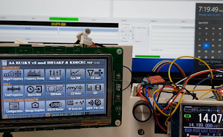
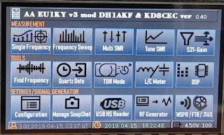
Release EU1KY AA Firmware CEC Version 0.40 ( How to using WSPR, FT8, JT65 TX Mode)
This version is a development version and may be unstable, and some of the features included in this version may be removed from V1.0, Stabilized version V0.35 has been released, and stabilized version is posted separately.
stabilized version : http://www.hamskey.com/2019/03/eu1ky-antenna-analyzer-cec-stabilized.html

When this version stabilizes, I will change version number to V0.45.
1. Added or improved in V0.34
Please see the link below for revisions and improvements until Version 0.34
(Do not download the firmware from the above page. old version)
http://www.hamskey.com/2019/03/released-eu1ky-antenna-analyzer-version.html
Please see the link below for revisions and improvements until Version 0.21
(Do not download the firmware from the above page. old version)
http://www.hamskey.com/2019/03/release-firmware-cec-version-021-for.html
(Do not download the firmware from the above page. old version)
http://www.hamskey.com/2019/03/released-eu1ky-antenna-analyzer-version.html
Please see the link below for revisions and improvements until Version 0.21
(Do not download the firmware from the above page. old version)
http://www.hamskey.com/2019/03/release-firmware-cec-version-021-for.html

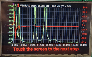
1.1 Added speed control function of Auto (fast) mode in Frequency Sweep mode
You can change the speed when operating in 'Auto' mode in Frequency Sweep mode.
'8' means speed up to V0.34 (Default Value)

If you change it to '16', you can see the value that changes close to real time.
As the speed increases, the measurement interval becomes wider, and the interpolation method instead guesses the value between.
If you set it to 4, the speed will be slower but it will be more precise than the existing one.

Below is an example of setting to '16'.

The measurement is executed in 0.5 seconds or less, so it looks almost real-time.

For precise measurement, stop the 'Auto (Fast)' mode and click the Scan button.
Below is a test video of this function.
1.2 Extend measurement frequency range in S21-Gain (VNA)
I have expanded from the existing 100Mhz to 1Ghz.
I recommend measuring this function only from 0 to 100Mhz, 0 to -40dB.
However, because users wanted to see a wide frequency range, they increased the measurement range to 1 GHz. At 100Mhz or higher, measure to -30dB only.

1.3 Added speed control function of Auto (fast) mode in S21-Gian (VNA)
'S21 AUTO SPEED' has been added to the setup menu. This menu does not affect AA, so you can change it as you like.
You can change the speed when operating in 'Auto' mode in S21-Gain(VNA) mode.
'8' means speed up to V0.34 (Default Value)
'8' means speed up to V0.34 (Default Value)

If you change it to '16', you can see the value that changes close to real time.
As the speed increases, the measurement interval becomes wider, and the interpolation method instead guesses the value between.

If you set it to 4, the speed will be slower but it will be more precise than the existing one.
Minimized blinking by minimizing the newly drawing area in V0.4.

Refresh to 0.5 seconds or less, so it looks like real time.

Test Video
1.4 WSPR, FT8, JT65 Transmitting function
This function can be used for setting up for digital communication, testing the connection between a radio and a computer, and measuring the reception performance of an antenna.
Or, if you add a simple amplification circuit, you can use it as a WSPR beacon.

1.5 Other changes
- The remaining balance (%) of the battery was added at 0.34.
(Removed by user's request, added back by user's request)
- The +200, -200 buttons have been added in the Si5351 Corr setting at 0.34.
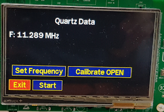
- Added touch function in Quartz measurement function. (When the RX screen is displayed, the user's touch moves to the next step. - user's request)
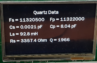
(When using this function, I have found a problem that I need to set the frequency and change the frequency. We are going to fix it in V0.5
(Be sure to change the frequency and use the function. Version 0.5 will be improved)
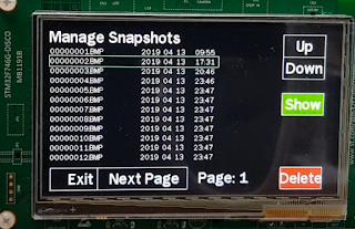
- In the 'Manage Snapshots' view screen, you can select a file name by touch.
(user's request)
- There are several other Minor updates.
(Memory cleanup, Name change 'S21-Gain Calibration', resize and realign buttons in S21-Gain for easy touch 'Auto', Fixed bug that screen turns off in configuration - Sleep mode section, To prevent entering 'Sleep mode' in 'Auto mode' of Frequency Sweep and S21-Gain and mores...)
(Removed by user's request, added back by user's request)
- The +200, -200 buttons have been added in the Si5351 Corr setting at 0.34.
- Added touch function in Quartz measurement function. (When the RX screen is displayed, the user's touch moves to the next step. - user's request)


(When using this function, I have found a problem that I need to set the frequency and change the frequency. We are going to fix it in V0.5
(Be sure to change the frequency and use the function. Version 0.5 will be improved)

- In the 'Manage Snapshots' view screen, you can select a file name by touch.
(user's request)

- There are several other Minor updates.
(Memory cleanup, Name change 'S21-Gain Calibration', resize and realign buttons in S21-Gain for easy touch 'Auto', Fixed bug that screen turns off in configuration - Sleep mode section, To prevent entering 'Sleep mode' in 'Auto mode' of Frequency Sweep and S21-Gain and mores...)
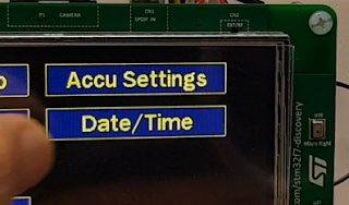
2 How to using WSPR, FT8, JT65 Transmitting function
touch the 'Configuration' button
touch the 'Date/time' Button
touche the 'ok' on any date
The date is not important. You do not have to match today's date.
Set the minutes. Press the 'OK' button when it is 0 seconds.
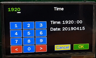
Look at the time at the bottom of the desktop and make sure the minutes and seconds are correct.
2.1 Change Time
You can use it without setting the time, but if you set the time, you can use the digital mode more conveniently.touch the 'Configuration' button

touch the 'Date/time' Button

touche the 'ok' on any date
The date is not important. You do not have to match today's date.
Set the minutes. Press the 'OK' button when it is 0 seconds.

Look at the time at the bottom of the desktop and make sure the minutes and seconds are correct.

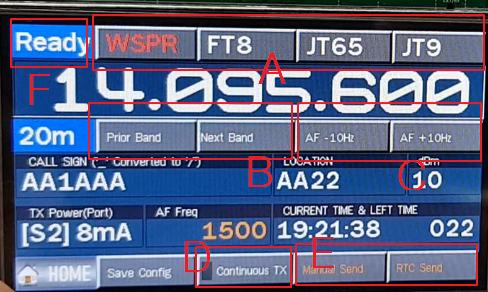
Touch the upper button 'WSPR/FT8/JT65' button
2.2 Change Mode
This function can use WSPR, FT8, JT65, JT9 protocol.touch the upper button 'WSPR', 'FT8', 'JT65', or 'JT9' to change to the corresponding protocol mode.
[WSPR]

[FT8]

[JT65]

[JT9]

2.3 Input data for digital Mode
The data for WSPR is Callsign, Location, dBmTouch the 'WSPR' button
Touch the Callsign Area

Input Your Callsign.
If you need '/', type '_'. If you have entered everything, click the 'OK' button.

touch the Location Area and Input you Location
input dBm Area and Input dBm
For FT8, JT65, JT9, only the text data to be transmitted is required.
If you enter only one, all protocols will be used together.
Touch one of 'FT8', 'JT65', or 'JT9'.

Input 'Text Message'
Ex) Your call sign and your location

Save configuration information
Only the 'Save Config' button must be pressed to save the set information to the SD-Card.

Even if the AA is turned off and then turned on, the setting configuration is loaded.
2.4 Send Data
Select Protocol for transmission. (A)
Please select a band to transmit (B)
If you want to adjust the frequency, use the AF-10Hz, AF + 10Hz buttons(C)
WSPR should not deviate significantly from 1500hz.
Please select a band to transmit (B)
If you want to adjust the frequency, use the AF-10Hz, AF + 10Hz buttons(C)
WSPR should not deviate significantly from 1500hz.

Transmit option #1
If your 'AA' does not have the correct minutes and seconds, watch your wristwatch and press the 'Manual Send' button if it is time to transfer
The 'Manual Send' button is changed to the 'Stop' button and you can interrupt the transmission at any time using this button.
The status changes from 'Ready' to 'On air'.
Transmit option #2
If your 'AA' has the correct minutes and seconds set, press 'RTC Send'
The status changes from 'Ready' to 'Wait ..', The transmission will start automatically when the time is available for transmission. Please wait a moment.
If you want to stop the transmission, click the 'RTC Send' button again.
If the transmission time according to the protocol is reached, it will be transmitted automatically.

If you want to continue digital transmission, you can use the 'Continuous TX' function.
(D)
Click the 'Continuous TX' button and the square will change to blue.

If you press 'RTC Send' button, it will continue to be transmitted until you press 'Stop' button.
Maybe you can use it to measure the performance of the newly created antenna.
2.5 Test for digital TX
QRP The spectrum when receiving from the transceiver. (Change Frequency)
It has been decoded in Wsjt-X 2.0.

2.6 Change transmit port
S1 and S2 can be selected as transmission ports.S1 outputs a very weak signal.
Touch the TX Power area below.

The TX port and power will change.


It may be possible to efficiently test the reception performance of the antenna by leaving 'AA' at a considerable distance and outputting it to S1.
2.7 Application
I do not know if someone needs PTT, so I added some features. If you need a PTT for hardware retrofit, you can use GPIO B4.
GPIO B4 becomes HIGH when WSPR, FT8, JT65, JT9 are transmitted.
In the above video, there is an LED, which is the LED connected to B4.
This is just your choice. I do not need it now, but I just implemented it because somebody might not need it.
3. Download Firmware
4. conclusion
I would appreciate it if you test and give feedback.
If there is no problem after 1 week ~ 2 weeks test, version name will be changed to stable version.
If you want a stable version, please use the link below.
If there is no problem after 1 week ~ 2 weeks test, version name will be changed to stable version.
If you want a stable version, please use the link below.
Thank you for your test.
Ian KD8CEC
Thanks, Ian! All works fine.
ReplyDeleteExcellent
DeleteThank your for your test.
Ian KD8CEC
Hi Ian,
ReplyDeleteAll works excellent.
73! HA8NJ Janos
Janos
DeleteThank you for testing
This version will probably be able to be renamed to a stable version without any modifications.
Ian Lee KD8CEC
Tested all the features. Everything works fine. Perfectly!
ReplyDeleteIn the future, I think it is necessary to compare the design on all screens. Although, to make the buttons the same. Thanks for your work. Not an analyzer, but just a fantastic car. Soon will turn into a transceiver ...... Hi..hi
Justas LY2BOK
Justas
DeleteThank you for always doing the test.
I'm glad that there are those who test.
I will put your opinion in the Todo List.
Ian KD8CEC
I'm glad about the new functions, especially the new measurement speed modes.
ReplyDeleteA ham friend told me to test the Bluetooth connectivity, so I programmed a HC-05 serial to Bluetooth adapter with 38400 bd, wired as follows:
3V3 - CN6-4
GND - CN6-6
TX - CN4-1 (D0) , RX USART6
RX - CN4-2 (D1) , TX USART6
After pairing with my Laptop's Bluetooth (code is 1234) I could connect with the program "Hamscope" and send commands, get the results on the laptops screen.
Now my question: Could you speed up the measurement process, also with Bluetooth connection, Ian?
Happy Easter,
Wolfgang
Wolfgang
DeleteIt is wonderful. I love using Bluetooth, too and i also have some bluetooth modules.
The measurement speed is made by widening the measurement interval as you well know. It is not difficult to measure it by using USART. I'll test it soon.
Thank you for your kind comments.
Ian
Hi OM Wolfgang and Ian. I have modified the EU1KY VNA v3 Board incorprating the recent HW and FW Mods like :
Delete1. Header for Battery Voltage (two 1K Divider )
2. Header for CLK02 Pin for S2 Port.
3. Header for Connecting Bluetooth Module
4. Header for Buzzer with a Buffer using 2n3904 , for protection of the STM Board and provision of putting bigger Buzzer.
I have put the layout JPG in the below link. If you both could spare some time to review the changes, I would be able to place the PCB fabrication order after any changes you suggestions and also release back the .Lay and Gerbers for the public. I would love to send you the modified PCBs for your next build, as my gratitude towards great work done by you both on this wonderful project.
https://photos.app.goo.gl/NhvYYts5BgaKhtqF6
https://photos.app.goo.gl/fdhmuLa7ddc8WBSL8
Hi, OM John Ujjwal,
Deletea very nice work!
But for point 1.) I would suggest 10 kOhms instead of 1k.
And I would suggest much more via's to the ground.
73, Wolfgang
Ujjwal
DeleteIt is wonderful.
I plan to add two GPIO Outs and two GPIO Inputs.
GPIO Out : B4, I3
GPIO In : PG6, PG7
Whether or not to use it has not yet been determined. And this is not essential. we can solder the wire directly.
If there is a lot of empty space in the PCB, consider it.
Ian KD8CEC
Thanks Wolfgang for your review of the PCB changes and suggesting changes.
DeleteIan, the wrong value of Voltage Monitor Voltage Divider Resisters was due to copy-paste of the component (somehow I dont like Sprint as much as Eagle) . I have made the change in its value, plus added more Ground Via (still not complete , will add in the empty area the way I have added in most of the PCB ).
Currently the PCB looks like in the link below. I still to add header for RTC clock module.
(No uploading the Bottom Layer photo which has some tracks like that for the Bluetooth header , GPIO header and Buzzer buffer amp using 2N3904)
https://photos.app.goo.gl/UjcMcb92WNHaaQRe6
It works excellently! I joined the antenna and tried WSPR. Many stations from Europe saw me at 40 meters. At 20m Iceland. That's nice with a power of 10 mW. It is the world's first antenna analyzer that can do such things. :-)
ReplyDeleteMirek
DeleteExcellent
I have confirmed your WSPR log now. So cool.
Today I try to increase the RF output of the AA a little bit in a very simple way.
I will upload the test results.
Ian KD8CEC
Hi Ian and the others.
ReplyDeleteI tested the S21 Gain according to the precision generator and the Wandel & Goltermann level meter.
I measured these levels:
0 db 0 dB
-10 -2
-20 -12
-30 -22
-40 -32
-50 -42
-60 -52
The result is obvious - the mixer is overdrived.
The solution is easy. It is necessary to include the attenuator 10 dB in output S2 and recalibrate.
Mirek
DeleteThanks for the good info.
Maybe this is due to the characteristics of the instrument used.
I think it's a good idea to add -10dB in some cases.
I was pretty good at -40dB when I used an attenuator.
Of course, the accuracy is lowered when it is over 200Mhz
In my case, the range of dB available for adding an attenuator is further reduced.
I am looking forward to various tests, and these tests are helping me a lot.
Thank you again
Ian KD8CEC
Hi Mirek,
DeleteI am myself not able to get S21 Gain feature not working , where I am getting all my plot Truncated on the either extreme end of the Scale of the Graph (Please see the Photos) . Do you think even I need to put a 10dB Attenuator ?
With S2 and S1 bridged with Coax:
https://photos.app.goo.gl/f8FSdGyP8EpYpoiP7
With S2 and S1 not connected together.
https://photos.app.goo.gl/4Lt16A9MZgSTXZsj6
The S2 port connected to 100Mhz Scope while scan in progress.
https://photos.app.goo.gl/N8EWTUYGdACuSS3B6
Ujjwal
DeleteWhat version are you using?
Please update the 0.4 version and try the new calibration. Probably the calibration is wrong.
Ian KD8CEC
Hi Ian,
DeleteThanks for the reply. This problem is persisting since earlier version and even till v0.4 . I tried everything like complete HW and OSL calibration apart from S21 Calibration.
Strangely even with a 10/20/30dB attenuator, and adding a 100nf Cap in series to the S2 port , I get the same result.
Could there be a problem with my S1 port ? As I can see frequency Sweep from the S2 port on my Scope ?
- Ujjwal John VU3ECN
It wasn't an overdrive mixer. There are protection diodes at input S1 and output S2 at 3.8 Volt p/p. It cannot be directly linked. I removed the diodes and everything is perfect. I'll try to put two diodes in series.
ReplyDeleteMirek
DeleteIt is a clear answer.
It would be better to install one DC Blocker (10 ~ 100nF Serial Capacitor) rather than a diode.
Ian KD8CEC
Yes, I have serial capacitor 100 nF on S2. But on S1 I had antiparallel diodes according to the original EU1KY design.
ReplyDeleteMirek
DeleteOK, i see. Your experiments and improvements will be of great help to those who have connected the diodes to the connector side.
I will add this content to my S21 Mod method.
Thank you
Ian KD8CEC
To John Ujjwal:
ReplyDeleteMy proposal for better matching the 50 Ohm of CLK0, CLK1:
R6 - 43 Ohm
R14 - 10 Ohm
R13 - 43 Ohm
R12 - 7 Ohm
Please correct: R4 = R11 =5.1 Ohm
What levels of DSP do you get with these values?
DeleteReducing the attenuation of the signal into the SA612.
DeleteI wonder if there was a performance improvement of S21-Gain when using this mode. Increasing the input signal of SA612 may affect S21 measuring gain.
With these modifications I got the folling results: (DSP mode)
ReplyDelete3700 kHz - Mag 2938 (@bin 107 10031 Hz)
145000 kHz - Mag 4457 (@bin 107 10031 Hz)
450 MHz - Mag 4408 (@bin 36 3375 Hz)
The idea to decrease the attenuation I got from LY2BOK.
There is another small problem - the input impedance S1 is not 50 Ohm. It is greater than 200 Ohm. It is not possible to change it due to the proper operation of AA. When used as a VNA, you must add an external load.
ReplyDeletehttps://yadi.sk/d/hPjskFoUgzfaqw
DeleteI solved this problem by applying this scheme.
i use BGA616 with 1uH coil in bias. annenuators tuned to 4-5V peak to peak output measured on the 50 Ohm oscilloscope.
RT6M
Mirek
DeleteThank you for good information. I was aiming for a minimal H/W mod with s/w calibration, but I am very happy to add more options to improve it.
RT6M
Thank you
I am interested in your Mod. Can you send me some performance measured pictures? I want to share it with other users.
Ian KD8CEC
This mod works well from 0.4 to 30MHz. It did not help eliminate noises above 30 MHz, they exist without mod and with mod But at least the output impedance became close to 50 ohms. I made this circuit switchable to a separate switch so that it does not consume extra current when I do not use it.
DeleteI will post a video here a little later.
https://youtu.be/ZnkQLsuStLo
DeleteHi Ian! This video is BGA616 Mod demo.
I think there is no need for HW mod, beauty is in simplicity. When I need it I add an external attenuator or load.
ReplyDeleteYes, Mirek. It's my small experiments for fun. I also wanted to protect the S21 output from external influences that could damage SI5351.
DeleteVery nice software for this beautiful instrument. I would like to mention some minor findings:
ReplyDelete- When i try to set the time for the RTC on second :00 to be able FT8 and WSPR, the time seems to set the seconds to a random number, but not :00.
- The mute button in the "Tune SWR" menu does not mute the buzzer on my analyzer.
73 Marten, PA3EKM
Nice work
ReplyDeletewishful feature
frequency generator: using S2
PCB integrating ESD protection S1 and S2 f.i. with GBLC03c
Time synchronizing pressing ok at 0 seconds does not set seconds at 0
73 Jaap