Installing SWR and RF Power Sensor in uBITX
I modified the I2C Type Signal Meter firmware to display SWR when using Nextion LCD in uBITX.Release I2C Type Signal Meter firmware V0.8, If you want something stable, use V 0.7
(V0.8 is a beta version)
Now if you are using the I2C Type Signal Meter, you do not need to update the uBITX firmware and the Nextion LCD GUI.
You only need to upload the firmware of the I2C Type Signal Meter to V0.8.
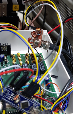
I plan to improve the Nextion LCD GUI to take advantage of this feature a bit, but I will keep it compatible with the existing GUI.
1.Creating a Sensor
Any sensor that outputs FWD (Forward) and REV (Reverse) analog can be used.
The voltage from the sensor is recommended to be less than 3 volts.
I have made a simple sensor.
It is a very simple circuit called 'Stockton Bridge'.
I made it in the form of ND6T which is used mostly by Bitx or uBITX users.
http://bitxhacks.blogspot.com/2017/03/nd6ts-forward-and-reverse-power-meter.html
Since there are quite a few PCB pieces, I have imitated the ND6T's SWR Bridge.
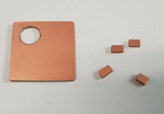
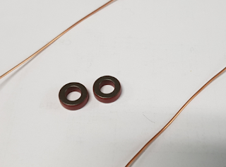
Anything that can use 1 ~ 50Mhz is okay with Core.
'Stockton Bridge' I made two for testing. The two are the same, but the Forward and Reverse outputs are opposite.
If you search for 'Stockton Bridge', 'SWR Bridge', or 'SWR Sensor' on the Internet, you can see quite a lot of things you can easily create.
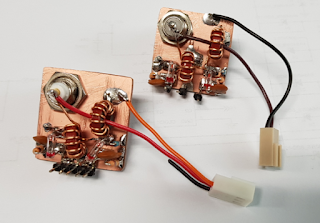
(Be careful of the direction when winding the coil on the core.)
2.Firmware
You can download the firmware file from the link below.
https://github.com/phdlee/dspmeterv1/releases/download/V0.80/CEC_I2C_Meter_V0.8.zip
If you need a source file, please click below.
https://github.com/phdlee/dspmeterv1/releases/tag/V0.80
For more information on how to update your firmware, go to http://www.hamskey.com
3.Connecting to the I2C Type Signal Meter
You only need to connect three additional wires to install it.
Connect FWD (Forward) of Sensor to A2 of I2c Meter.
(Red color line)
Connect REV (Reverse) of Sensor to A3 of I2c Meter.
(Blue color line)
Connect GND (Ground) of Sensor to GND of I2c Meter.
(Black color line)
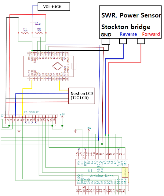
The picture below shows that I connected the white line for Forward, the yellow line for Reverse, and the black line for Ground.
CAUTION: Do not have long wires as shown below. Multiple noise and various problems may occur. Keep the wires as short as possible, It is recommended to use shielded wires.
I have a few uBITXs and below is a uBITX without a Case for development.

4.How to Use
If it is made simple without any shielding as above, 1.5 or less and 3.0 or more are inaccurate. You can increase the precision by using metal shields between Forward and Reverse when creating the sensor.
But I decided to use it as it is. This is enough for a simple SWR meter on a transceiver.
It works the same way as DSP Signal Meter. Therefore, first check if the DSP Signal Meter is operating normally.
The I2C Meter relays the data between uBITX and Nextion LCD.
When there is no data to relay (as IDLE time), the I2C meter measures the signal and transmits it to Nextion LCD.
The I2C Meter will relay the data and will detect that uBITX is in TX state. At that time, the Forward and Reverse signals are read, converted to SWR, and transmitted to Nextion LCD.
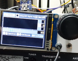
SWR : 1.0 ~ 1.4
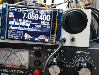
SWR : 1.5 ~ 2.4
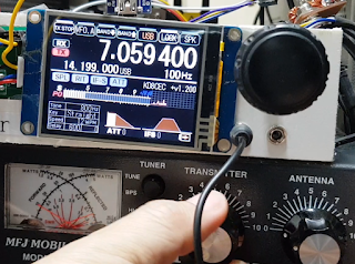
SWR : 2.5 ~ 3.4
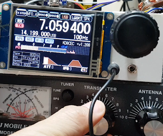
SWR : 3.5 ~ 4.4
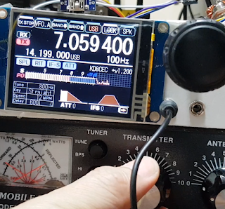
SWR : 4.5 ~ 5.4
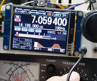
SWR : 5.4 ~
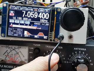
SWR : infinite
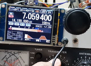
I tested it with MFJ-945 and Diamond SX-600. For SWR 2.5 and above, the two SWR values are displayed quite differently. The sensor I made was more like the one measured on the SX-600
5. Test Video
Thank you for reading
Ian KD8CEC
Hi,
ReplyDeleteHow do I change from SWR to FWD?
Thanks.
Flavio
DeleteSWR is the only measurement yet.
To measure the FWD (RF Power), need to modify the Nextion LCD or uBITX firmware because it requires some option values.
Maybe if I make the next version, Nextion LCD will set the parameters for power measurement.
If it does, RF-Power will also be displayed.
Ian KD8CEC
Are you sure the diagram is correct ? The picture above shows the yellow and white SWR and FWD lines connected directly to the second Arduino and not the Raduino. Which one is correct?
ReplyDeleteThanks
Agree
DeleteG7JUR
I also noticed that, I think it should be connected to the second Arduino.
ReplyDeleteThe video shows clearly that the FWD and SWR lines go to the first (extra) Arduino.
ReplyDeleteI've done the mods but when I transmit, the power meter (Nextion) shows full scale deflection with nothing hooked up yet. Only GND, 5V and A7 with capacitor to potenciometer and Nextion connected in series with the extra Arduino.
When I connect the two A4-A5 wires to the radio's Arduino nothing changes.
Prior to that, I followed the standalone Signal analizer instructions and the A5 and A4 lines should be wired to the ubitx's Arduino A5-A4 ports as well.
When I first fired up the ubitx with the new addition(S-meter only) I forgot to connect
A4 and A5 but everything worked without them.
What are they for in the first place?
Am I doing something wrong?
Thanks
Hi!
ReplyDeleteCan't make it work. I was wondering if we all are using the wrong version.
In the video I see you're using ver 1.2 instead ver 1.097. I measured the
A4-A5 lines when I press the PTT to see if they are used to tell the I2C meter that it's in TX state but what I get is 5 volts on A4 and 3.3 on A5 during TX or RX no change at all.
You said above ''The voltage from the sensor is recommended to be less than 3 volts''
How come A4 is sending continuos 5V to the I2C?
I may have damaged the A4 on the I2C meter by now.
Thanks
Thanks for your continued efforts on the firmware! I have not been able to get this to work, the 2nd arduino is reading values ok, measuring amplitudes and talking to the raduino, but SWR indication is not on the meter, and the CW decode function/frequency display isn't working. Band scan etc works fine. I think this might be due to an old/incomplete TJC firmware version. I use a TJC 2.8" non extended on my rig, with latest firmware release I could find. Latest github versions for the 2nd and raduino. See my website mw0uzo co uk for pictures of the rig. Would be great to get this working!
ReplyDeleteHi Ian.
ReplyDeleteThanks for the VSWR firmware.
I have built a VSWR bridge, and fitted it to my uBITx V5.
Working well, now waiting for some updates to this.
Regards Philip G7JUR.
Hi Ian...
ReplyDeleteIs PWR/SWR functionality available on LCD screen or Nextion only?
73
Gerry
I will be studying this. I'm a little behind as I purchased an Icom7300 and have been working with it. I'm back here because Ashhar Farhan has his own antenna analyzer using a Nano, bridge, other circuitry , very compact (said it was the only one that would fit INSIDE of his cube sat) , and ever increasingly interesting software. Tracking Gen, Spectrum analyzer of sorts, ect. Signal measurement capability, a sensitive signal measurement function , and much more. I"d need to check what you are doing with the one in here, and the EU1KY AA antenna analyzer you work with to see if either have done these things. If you are interested in what he is doing with his "antuino" here is a link, to a few videos. A good description , functions list http://www.hfsignals.com/index.php/antuino/ And, here is the link to the software : https://github.com/afarhan/antuinov2.1 Usually , Ashhar's circuits have far more complexity and capabilities than the software he writes. You've done so much with his uBITX , I'd like to see what you do with this. N6GRG
ReplyDeleteI'm a little confused.
ReplyDeleteWorking with this on a v6, the display header only has 14 pins, the Nextion is connected to 1, 2, 5 and 11.
The prose suggests that the only connection between the second Arduino and the Raduino is the I2C (A4,5), however the schematic shows D8 to D13 being connected to the display header, which is connected to the Raduino though it does not look like the same pins are connected to each other (i.e. D13 to D13).
All input is welcome.
73
KK7BCO
Such an amazing blog with an detailed informations thanks for saring this Custom ERP Software
ReplyDeleteEasily the best post ever made. To learn more about us and the services we provide, please visit: Merchant Cash Advance Leads Paving the Path to Financial Success. Merchant Cash Advance leads are prospective clients actively seeking alternative funding options for their businesses. These valuable leads present MCA providers with a golden opportunity to cater to the specific financial needs of businesses, fostering growth and prosperity in the ever-competitive commercial landscape.
ReplyDelete