uBITX Firmware CEC Version 1.097Beta Release
(Include Nextion LCD, TJC LCD GUI Firmware V3, uBITX Manager V1.097,
Standalone Signal Analyzer1 V0.7)


1.Installation and Introduction


Standalone Signal Analyzer1 V0.7)
Changed Standalone Signal Analyzer1 V0.5 => Standalone Signal Analyzer1 V0.7
uBITX firmware CEC Version is based on uBITX which has not modified anything. Prior to deployment, the 16x02 LCD with built-in is tested first. Nextion LCD, TJC LCD, 20x04 LCD and I2C LCD are not essential for using uBITX Firmware CEC version.
In order to view signals with Character LCD or Nextion LCD, Signal Meter Sensor must be installed. Of course, CEC Firmware operates normally even if S-meter sensor is not installed.

Standalone Signal Analyzer changed from Version 0.5 to 0.7
If SSA (Standalone Signal Analyzer)'s default mode is set to Spectrum, Spectrum will be displayed on the screen as soon as power is turned on.
At this time, there was a problem that the amount of data transmitted from uBITX to Nextion LCD exceeded the default buffer of SSA. SSA 0.7 solved this problem by activating the Spectrum function after waiting for about 2 seconds after starting up.

1.Installation and Introduction
The link below contains installation instructions and basic usage, so this post will briefly explain the changes.
1.1 Select .HEX file for uBITX

prefix : UBITX_CEC_
Version : Vxxxx (ex: V1.097)
LCD Type : _XXX (ex: 16x02 Parallel = 16P, 20x04 Parallel = 20P, 20x04 I2C = 20I, Nextion LCD = NX)
Signal Meter Type (Option) : none : Analaog Meter using A7 PIN
_S : I2C Signal Meter using I2C Port
When I2C type signal-meter sensor is used, end of filename ends with _S.
1.2 .Hex file for Standalone Signal Analyzer (I2C Type Signal-Meter) & Installation DSPMeter1_V0.5.hex
2.uBITX Firmware CEC Version 1.097 and Nextion, TJC LCD GUI V3 Download
Precompiled .HEX files
Nextion LCD GUI Files (include gui sourcefile (.hmi), precompiled (.tft))
Officaial Support 2.4", 2.8", but include 3.2, 3.5 for test (just converted from 2.8")
I have added 2.4".TFT files and uploaded again. If you are using 2.4", download again.
TJC LCD GUI Files (include gui sourcefile (.hmi), precompiled (.tft))
Officaial Support 2.4", 2.8", but include 3.2, 3.5 for test (just converted from 2.8")
Nextion LCD GUI Template file for Developer, The Template file is a blank screen that only communicates with uBITX.
uBITX Manager Version 1.097
Standalone Signal Analyzer1 (I2C Type Signal-Meter) V0.5 => V0.7 (Changed)
Since uBITX firmware source files will continue to change, we will push to github when the beta period ends.
Standalone Signal Analyzer1 (I2C Type Signal-Meter) V0.5 Source code
3.Changes and improvements
3.1 Bug fixed (for all LCD version include character LCD)
minor bugs
3.2 uBITX Manager removed the Encode and Decode buttons. The procedure has become a bit easier. (uBITX Manager Version 1.097)

3.3 I2C Device Scan


3.4 Recovery using QR-Code Data from Server
This part will be posted separately.

3.5 Si5351 I2C address can be changed
You should not use it in general. If your I2C address is not 0x60, you can modify it here.
You do not need to use it if your uBITX is working normally

3.6 Support Standalone Signal Analyzer (I2C Type Signal Meter)


3.7 Nextion LCD and TJC LCD can display Spectrum and CW Decode.
To use this feature, you must use the Standalone Signal Analyzer.


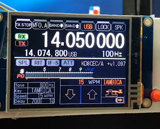
3.8 CW Options settings in Nextion LCD (TJC LCD) using Touch


more information :
3.9 Quick Menu for CW in Nextion LCD (TJC LCD)


more information :
3.10 UBITX source code modification for developers
It was an idea from the bitx group two or three months ago.
I have added an option to deactivate each function in the source code.
This part will be posted separately.
4.Conclusion
This version is probably the last version of the beta version.
I am going to fix the bug and redistribute it to Version 1.1 if the problem does not occur.
I am always thankful to developers who are developing at different resolutions of Nextion and TJC.
This part will be posted separately.
Thanks for the great work Ian - One problem - the Download link to the "Standalone Signal Analyzer1 (I2C Type Signal-Meter) V0.5" hex file points to the MM1.097.zip, by mistake?
ReplyDeleteI can't download the Signal Analyzer hex file.
73
The link for the source works.
DeleteVK3XPT
DeleteThanks for information.
I fixed it, you can download 'Standalone Signal Anylzer1' now, please try agian.
Gregory Keys. Thanks for another solution.
73
Ian, KD8CEC
Thanks Ian!
DeleteI have everything loaded up, and working very nicely here :)
Thanks again!
Perrin VK3XPT
Hello Lee,
ReplyDeleteI am sightly confused with this description appearing in your source file ubitx.h.
The confusion is in the Clock output pins on this header. All schematic show it as CLK2 - CLK1-CLK0, but you have shown it reverse. Is this a typo or is this factual.
* The second set of 16 pins on the Raduino's bottom connector are have the three clock outputs and the digital lines to control the rig.
* This assignment is as follows :
* Pin 1 2 3 4 5 6 7 8 9 10 11 12 13 14 15 16
* GND +5V CLK0 GND GND CLK1 GND GND CLK2 GND D2 D3 D4 D5 D6 D7
Charudatt.
DeleteThanks for Good information. i will fixed this comments. Thanks
Ian KD8CEC
works great, tnx for the CW options.
ReplyDeleteKees PA5CW
Thanks for Beta Testing.
DeleteIan, thanks again for all the work you put into this development!! I am at work right now, so can't get this installed on my uBitx until tonight. I also have to build the 2nd arduino circuit. I have copied all the files I need, the firmware upgrade, the Nextion tft files for my 2.8 display (well the whole file set), the uBitx Manager updated software and the Standalone Signal Analyzer to a thumb drive. Again appreciate all this work that you have done. Really glad that now when I want to work CW and choose which key type I want has been made easier to get to.
ReplyDeleteThanks
Juddie WD8WV
When you have time, please test and let me know. I would probably end the beta with this version.
DeleteIan KD8CEC
Will do Ian. Been cutting grass and cleaning up around home. Will try to get everything done and tested I hope by the weekend.
DeleteJuddie WD8WV
I also built the Arduino Nano S-meter, but reversed back to older version and de-soldered everything because I was mixed up how to configure it in Ubitx Manager.
ReplyDeleteI piggypacked both Arduinots to avoid electrical noise and/or long signal lines.
However the set-up makes hell of a noise when turning the VFO, hiss, pop and crash.
Is it due to i2C communication or what?
I appreciate Ian's genius work but at this stage I feel a bit tired. I have helped other fellow hams to upgrade their Ubitx radios and found out that SEARCHING for software files is quite hard.
Ian, could you put all your s/w files, including Nextion files somewhere where we could find
them easily. This is just a humble plea.
Kai OH3WE
Kai
DeleteThanks for testing and comment about that.
Noise => there are two places where noise occurs. The first is the communication line. Second is LCD.
If you hear 'tick, tick' when you turn the VFO, this is the noise that appears when communicating. Actually, now I also hear 'tick tick' sound when uBITX remove the antenna (To create a quiet environment), increase the volume, and dial the VFO knob.
It is not a big problem for me and I am using it as it is.
I have a few things to experiment with about this. I'll post it if I can experiment later and get better results.
The second is the noise from the LCD. This will continue to generate noise, mainly in the Spectrum mode.
This is the noise that occurs even in normal times, which is an obstacle to communication. Connecting a 5ohm ~ 15ohm resistor in series with the + 5V line on the LCD will disappear cleanly.
For this, I posted it on the link below.
http://www.hamskey.com/2018/08/standalone-signal-analyzer-i2c-type.html
I have also tested transmission and confirmed that it is being transmitted cleanly.
I think these things can work together to make a better radio.
for Download Files
The file is mainly registered on https://github.com/phdlee/ubitx/releases
All my versions can be found above. I registered in my blog now because it is a beta period. At the end of the beta period, we will register for the above 'release section'
I also post the explanatory material first and then release the version to avoid confusion. When publishing the description material, I will add a pre-distribution phrase.
Ian KD8CEC
Hello, have a problem with my uBitx LSB/USB modulation. Up 10Mhz must be USB modulation, below 10Mhz - LSB. in my case is reverse: example. if I want to hear clear signal in 14Mhz I must to switch to LSB modulation,or in 7Mhz - USB.
ReplyDeleteWhere is the problem? Thanks.
LY5SB
DeleteIf you tell me when your firmware version and its symptoms have appeared, I will be able to make a more accurate judgment. If you send your uBITX backup file, you can judge it more accurately.
But I have seen a lot of such symptoms. Most of the symptoms were after trying to calibrate.
You can solve your problem by clicking the link below. http://www.hamskey.com/2018/05/introducing-ubitxs-invalid-calibration.html
I dont know because everything was fine until I connect ubitx with ubitx manager program.I did not make any changes only write cw memory key text.thats all...
DeleteMy firmware is V1.08
DeleteDo not worry. In most cases, the calibration value is wrong. Please follow the link below. If not, please send uBITX backup file to me.
Deletehttp://www.hamskey.com/2018/05/introducing-ubitxs-invalid-calibration.html
To add one more explanation, if you were normal before you updated the CEC Firmware, you could easily get back to the original state.
DeleteUse Factory Reset.
Good Morning Ian, I got the mod working!!! I love it Ian!! Now I haven't cut the yellow line yet coming from the Nextion to the new arduino. I will do that tomorrow evening, but I am liking this. Everything seems to be working just as it should. I figured the DSP part wouldn't work until I cut the yellow wire and connect it as you have shown. Again thanks for all your extremely hard work! Juddie WD8WV
ReplyDeleteLooking for the source code. Thanks!
ReplyDeleteHello Ian, here most things work very well with the new firmware. Many thanks!
ReplyDeleteOne exception: cw transmission does not function correctly . I could not find a single
keyer that produced good results. Often there is not even change from rx to tx.
Regards Heiner
This comment has been removed by the author.
ReplyDeleteThis comment has been removed by the author.
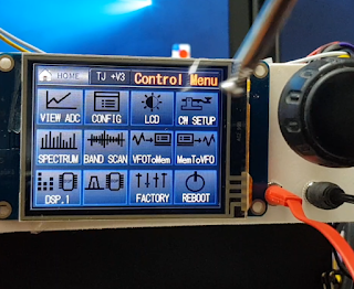
ReplyDeleteIan...I have downloaded the 1.097 firmware, unzipped it, and uploaded the 1.097 NX S version onto Raduino. Everything appears to work normally, and the Home page correctly displays +v1.097. However, when I switch to the control menu, there is no DSP button...what have I done wrong??
ReplyDeletethanks for this new update
ReplyDeletethanks for this new update
ReplyDeleteBuilt-in Power Supply Voltmeter
ReplyDeleteIan, I'd really like to see a voltmeter reading incorporated into the TJC/Nextion touch screen home display for use during battery power operation. I've devised a possible way of making double use of the A3 input, currently being used only for the PTT discreet. If a 220K resistor is connected from +12V supply voltage input to the A3 input of the Raduino and a 100K resistor from the A2 input to GND, this should provide a voltage of approximately 5 volts at A3 when the supply voltage of 16VDC to allow for an indication for if the supply exceeds the 15VDC maximum voltage rating of the circuits).
Since I am not a programmer it would require someone else to write the code for the reading of the analog signal to A3. Calibration of the input would require only the input of a user supplied meter reading and the analog reading of A3 (possibly automatic). It would be nice if this entry could be made through a screen accessed through the "Control Menu" (I've noticed there is an unused button on this screen).
Craig, N1HI
Hi Ian,
ReplyDeleteI have noticed a couple glitches in the Nextion/TJC screen operation:
+ When the "TX STOP" button has been activated before going to the "Control Menu" and making changes in the "CW SETUP" screen, when returning to the "HOME" screen the radio will transmit, even though the "TX STOP" button still shows active ("STOP"). Also, when the radio gets into this mode, the "STOP" cannot be selected off.
+ Both "IAMBICB" key mode does not seem to be working, it is the same configuration as the "IAMBICA" selection (tip = dit, ring = dah).
Craig, N1HI
Hi Ian,
ReplyDeleteRegarding my comment about the adding a supply voltage monitor, the software version number could be moved to the "Control Menu" screen and the supply voltage reading could take its place on the "HOME" screen.
Craig, N1HI
Great work, thank You Ian!
ReplyDeleteI have a TJC 3.5" display, and the active screen area is like 2.8" . Is there a chance to
get full 3.5 coverage? I would try to make it myself but TJC editor is Chinese only.
Or should I go for a smaller display?
Best regards!
Zlatko, 9A5AZG
This comment has been removed by the author.
ReplyDeleteThis comment has been removed by the author.
ReplyDeleteThis comment has been removed by the author.
ReplyDeleteJust a note. After connecting the Nextion I found the touchpad working but not communicating with the rarduino. The reason is that the Nextion has a default speed of 38400 baud, forced to 115200 during the flash procedure. But if the firmware doesn't initialize in some way (and it seems that this initialization is missing) it is necessary to use command bauds=9600 (bauds not baud that set the speed also after power reset https://www.itead.cc/wiki/Nextion_Instruction_Set ).
ReplyDeleteI used nextion IDE to write on it, but it should be possible also via terminal .
PhD Lee,
ReplyDeleteI am mvs sarma vu3 zmv.
I am making a change in IF from present 12MHz to 9MHz. I could change the IF carrier, USB and LSB values to suit. But i would like to use s-meter. The published .hex codes work for 12MHz.
Please try if you could suggest changes in source code for re compiling the code for 9MHZ if Mod.
thanks in anticipation
regards
sarma
vu3zmv
is there a way to change the frequency numers color? like to green insted of white? i am a nob for programming and excited to learn this. I am very impressed! my nextion screen and ubitx v6 is on the way! i hope. thanks Amie n9oxo
ReplyDeleteGreat post also have a look on
ReplyDeletehttps://www.wamatechnology.com/top-ios-app-development-company-in-mumbai/
Hello Ian, I have a Ubitx ver4 with the Nextion NX3224K028_011 and all works great. I was just given a Ubitx Ver6 with the same screen but i can not make the files work with it. I put the file ubitx_28_E.tft on a blank formated sd card, but when I put the card into the screen and power it on the screen says file version to low. Any idea's what im doing wrong ?
ReplyDelete