Standalone Signal Analyzer (I2C Type Signal-Meter) for uBITX #3 - Advanced and FFT
3.Nextion LCD Advanced
This is the second part of the article below. Use the same equipment and sensors.
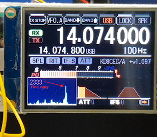
The video below contains various experiments of this function.
1.Disable/Enabled Signal Sensing on Standsalone Signal Analyzer
Touch the CW Information Pannel -> Touch the DSP.1 Button
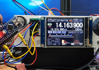
Select 'Using DSP Signal-Meter' on the screen below
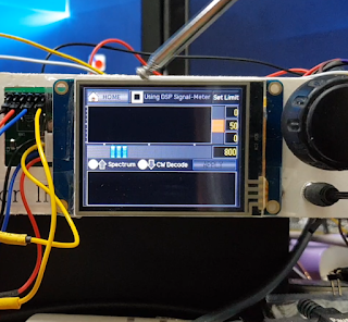
Touch the APPLY Button.
The signal sensor then independently measures the signal and delivers it to the Nextion LCD.
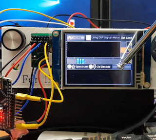
The signal is displayed on the LCD.
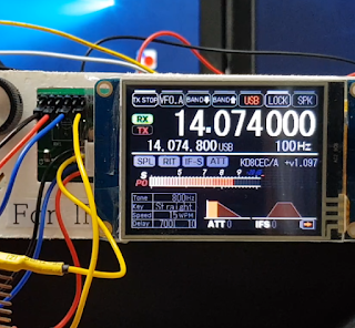
Touch the CW Information Pannel -> Touch the DSP.1 Button
deselect 'Using DSP Signal-Meter' on the screen below
Touch the APPLY Button
The signal meter will stop.2.Realtime Spectrum
I2C signal-sensor can output spectrum of 3Khz.
Touch the CW Information Pannel -> Touch the DSP.1 Button
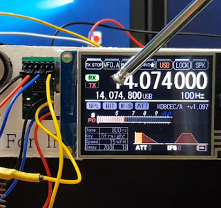
Select 'Spectrum' Icon
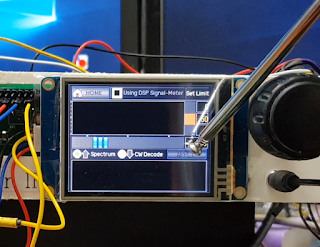
Touch the 'APPLY' Button
The LCD will display Spectrum.
You can see a spectrum of about 3Khz.
This does not affect uBITX, so real-time operation is possible.
Touch the 'HOME' button
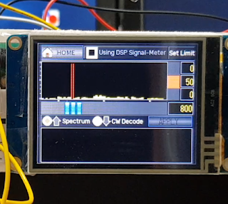
Spectrum will continue to be output from the Main screen.
Since it operates independently of uBITX, it does not affect transceiver operation.
You will not be able to see the communication status of other frequencies like SDR.
But it can be used in CW and digital communication.
We found active 5 station (FT8) from below spectrum

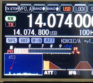
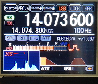
The number in the upper left corner of the Spectrum Window indicates the frequency of the strongest signal

The screen below shows that there is a signal in the 450Hz area.
The screen below shows that there are signals at approximately 800Hz and 2000Hz.
The resolution of the frequency is about 3000/32, so you can get an approximate position.
3.Morse code Decoding
I was able to find Morse code decode code using Arduino Nano on the internet. The code worked great and I applied it. Thanks to the developers who shared this cool code.
Go to the DSP.1 screen.
Touch the CW Information Pannel -> Touch the 'DSP.1' Button
Display the spectrum on the screen.
Select 'Spectrum' Icon, Touch the 'APPLY' Button.
Spectrum will be displayed as shown below. The following image shows the CW transmitted by connecting the MP3 to the transmitter for the experiment.
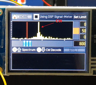
Move the slide so that the red line is on the CW signal.
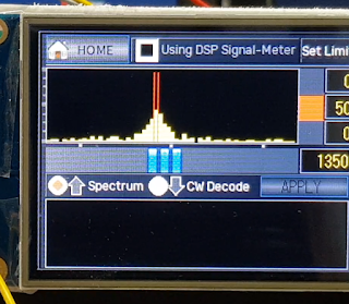
You will be able to see the CW signal moving in the red line.
Select the 'CW Decode' Icon.
Touch the 'APPLY' Button.
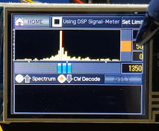
Spectrum will stop and CW Decode will start.
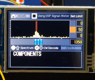
If the signal is weak and the decoding is not satisfactory, lower the level.
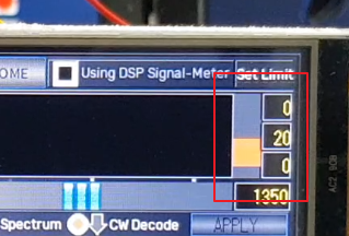
In DSP.1 screen, maximum 3 lines are displayed. If it exceeds 3 lines, it scrolls.
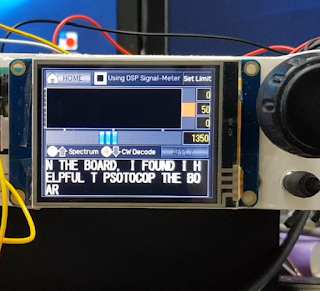
As with Spectrum, decoded CW characters are also displayed on the Main VFO.
Even if the power is turned off and then on again, the setting remains unchanged.
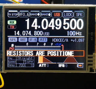
For reference, I keep Spectrum on.
I reduce the volume at the desk I am working on and occasionally check the Spectrum to check the radio condition.
The video below contains various experiments of this function. This is the same video from the beginning of this document. If you have seen it from above, you do not have to look again.
4.Noise in the spectrum mode
Maybe you can experience some noise in Spectrum mode.
First, make the length of the line between uBITX, Signal Analyzer Module and LCD as short as possible. Noise should have disappeared.
Second, Insert a 5 ohm resistor on the power line (red line) of the LCD.
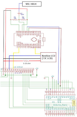
I could not reduce the length of the wire or shield it because I had to experiment continuously. So I used the second method and the noise completely disappeared.
The brightness of the LCD does not change much and the upload is good.
I have been using it for two weeks with a 10 ohm resistor connected.
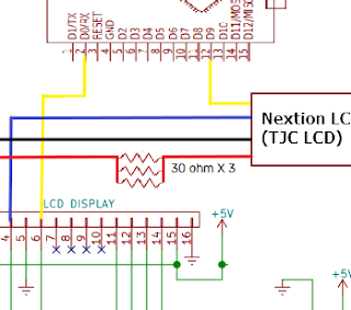
Note that the most resistors is 1 / 4W, so use 2 or 3 resistors in parallel
EX)
Thanks for reading.
I will now begin preparations for Version 1.097 deployment.
Ian, KD8CEC
Very nice information. Can't wait for the files to be available for download. I have already purchased the Arduino and have the resistors, capacitor to build this. So this replaces earlier versions of the s-meter using the LM386 or LM358 chip?? All of this done thru the Arduino correct?
ReplyDeleteGreat work Ian and all of us hams appreciate all this work you have done.
73
Juddie WD8WV
Yes, that's right. This eliminates the need to use Sensors created with LM386 or LM358.
DeleteI was planning to write another document and then distribute Version 1.097. But I will modify the plan and distribute the firmware first. If possible, we will upload all the source code.
Ian KD8CEC
Ian, I thought this posted last night, but I guess it didn't. Don't rush getting Version 1.097 out, if you are writing another document, concentrate on the document and release the files when your ready. I can wait for the official release.
Delete73
Juddie WD8WV
Ian, can I ask a favor?? Can you take a picture inside your uBitx that shows the wires you have coming out to hook to the second arduino? Did you solder those to the board? As I mentioned to a guy on FB uBitx page, I am more of a visual person when it comes to this stuff. Juddie WD8WV
ReplyDeleteJuddide
DeleteIf there is a connection between SDA and SCL, you can find the link below.
http://www.hamskey.com/2018/04/various-lcd-support-in-ubitx-with.html
If you need another picture, please comment it anytime. I can not take pictures because uBITX is not next to me right now, but I can send it within one day.
Ian
Hello, OM.
ReplyDeleteWhere is the software for another Arduino Nano. I'm so confused. Various files are scattered around and it takes a lot of scrolling up and dow to find the links.
i have updated my
-Raduino
-Nextion
Nextion is a 3.5 inch one but the file is for 2.5 inch display. A nasty drawback.
I wired up the DSP Arduino Nano, but can't find its software.
Thanks
OH3WE
OH3WE
DeletePlease refer to the link below, i posted version 1.097 and Signal Analyzer firmware v0.7.
http://www.hamskey.com/2018/08/ubitx-firmware-cec-version-1097beta.html#comments
Ian KD8CEC
Hi Ian, first of all I have to congratulate you for your success on ubitx improvements.
ReplyDeleteI have now my ubitx v.3 working with SSA very good.
But my nextion 3.5'' display does not showing full scale after I loaded v.1.097.
All functions are working fine but as a 2,5'' display.
I need your help.
Alper Ozmen
TA2FU from Ankara
I mean when I loaded ubtix_35.tft from UBITX_Nextion_GUI_V3
DeleteIan, I cut the yellow wire and did the connection to the second arduino and it is working perfectly!! I really like this modification using the second arduino!! Great work my friend.
ReplyDeleteSo far all I have done was tested it on 80, 40 and 20 meters, listening to voice communications, tuning to FT8 and some CW. Also, testing the decoder and that works great as well. Takes some practice learning how to maneuver around in the DSP window between Spectrum and Decode, but that isn't a problem. Once you learn the procedure it is a snap.
So far any noise I have detected is only when I have the volume down low, but once I increase the volume I really can't detect any noise coming in with the receive audio.
Now I just have to figure where in my homebrewed 7 inch x 7 inch by 3 inch enclosure to mount this board!! LOL I may have to build a bigger enclosure!!
Again thanks so much for all this work.
Juddie WD8WV
Hey Juddie - by luck I'd left just enough room to mount the 2nd Arduino to the right of the rotary encoder and gain pot, vertically on the front panel. The USB connector is therefore pointing up so any upgrades will be easy to achieve. The wiring is still a lash-up so much longer than necessary but I'm not getting any noise that I can hear.
Delete73 Martin - G4FKK
Martin, I was able to find a place to mount the 2nd arduino. I had some plastic standoffs and it is mounted just above the board about half way between the front and rear of the main board. It gives me easy access to the USB plug. I posted a video of the mod working, but no video of the permanent mount inside my rig that I built. My video is on my channel just called Juddie Burgess on YouTube. I really love this little rig. I plan on building my Version 4 board into possibly a Pelican case along with a Raspberry Pi so I can do digital as well. Still working on possible issues of heating up the finals.
DeleteJuddie WD8WV
Hello again Juddie, yes, that's a good place to put the 2nd board space-wise. I was a bit worried it might be a bit close to the 45MHz IF bits and pieces but the filter's screened and the toroids should be more or less immune so should be fine.
DeleteLike you I think this radio is brilliant - I love the fact the firmware is so hackable and so is the hardware to a large extent. The only thing it really lacks, in my opinion, is proper IF derived agc so I'm looking at building a new 12MHz IF 'strip' onto a small daughter board which I can mount above the existing. Having said that, I bet Ian comes up with a brilliant FFT solution at some point :-)
The other great thing is Ian having introduced me to the Nextion displays - I've got a load of stuff I've built using the usual LCDs driven by Arduinos or PICs and I'm busy re-writing the firmware to use the tft displays. I just wish I had Ian's talent for designing such professional looking layouts!
What will he come up with next I wonder?
All the best, Martin - G4FKK
Another triumph Ian! :-) Everything downloaded perfectly, second Arduino built and yellow wire modification done. All appears to work exactly as you describe. Thank you yet again for your brilliant work on this project!
ReplyDeleteVy 73, Martin - G4FKK
Okay, I been testing for a couple evenings now and I have had a few issues. One when maneuvering around the different menu items like going to the DSP option the radio would go into transmit! No mic hooked up or no key hooked up! I had to turn the radio off and back on to get it out of transmit.
ReplyDeleteI also have a steady noise that I can here if on a quite frequency. It increases if I turn the AF up. I put a 10 ohm resistor on the red power line from the raduino to the display screen. I also put the power and ground wire that goes to the second Arduino in a choke as well as the other two wires coming from the raduino to the Arduino in a choke as well.
Still have the steady noise.
Just curious, should I take 2 or 3 - 10 ohm resistors and hook them in parallel to the power wire going from the raduino to the display?
Juddie WD8WV
Hi Ian,
ReplyDeleteThanks for your remarkable work, this is a superb project. I have some feedback for you ..
1. I have seen a number of times the same issue as reported above by Judde WD8WV with regard to the rig going onto transmit while using the touch screen. If I use the encoder button menus it never plays up. (And yes, the key pullup is installed and checked with a meter).
2. Since adding the signal analyzer I have had problems with the Nextion not initializing either fully or at all. I added a bit of code to the Analyzer to turn on the LED on the board (D13, simply as a visual reference of when the delay ended) after the 2.5 second delay and had a look with the scope. Sure enough, there were times when the Radiouno sent data and the Analyzer did not loop through, no output at all. Once failed, resetting the Radiouno always fails, but resetting the analyzer, waiting a bit and then resetting the Radiouno always works.So I have used Pin D13 on the Analyzer connected to the Radiouno reset pin to hold off the Radiouno until the 2.5s delay has timed out - this works 100%, no further display problems. This, of course, is a patch - with your knowledge of the code maybe it's a clue as to what's going on.
3. I have noticed that the Analyzer s meter will sometimes 'stick' at what I assume is the last peak value measured when there is no or below threshold signal. As soon as there is enough of a signal to measure it frees up.
All the best, Dave G4SXT
Additional to above comment, I think I found a fix for the un commanded TX while using the touch screen. As part of my build I have moved all the 5v supply requirements for both Nano's and the Nextion onto a new linear 7805 regulator (Plastic tab version) which I have bolted to the metal case to provide good heatsinking. The Radiouno reg. was running very hot and could not find the room for a big enough heat sink.
ReplyDeleteThis touch screen now works fine, no issues at all.
I had un-commanded TX issues running the Nextion from the Radiouno, and when running the Signal Anayser + the Nextion from the new Regulator with the Radiouno using it's own reg. When I moved all three to the new reg it all worked fine,
can guess earth loop noise or mismatched levels being the problem ?
Set my profile up so I am no longer 'unknown!' Hi.
Just by the way, I had a long session on transmit today whilst checking the rig on the spectrum analyser and setting pa bias - no problem there, but along he way the Signal Analyser nano got wiped/corrupted. Re flashed it to fix. I have this well decoupled, nice short connections but the rf evidently got in somewhere....
73 de Dave G4SXT
Nice work. I am in the process of adding the second arduino and have found that I have an arduino mini pro. Could I substitute this for the arduino nano?
ReplyDeleteThanks
The more I read the less I know. Is there a page that shows wiring diagram for your newest firmware for 2.8 nextion and additional arduino.
ReplyDeleteI read your blog now share great information here. click read
ReplyDeleteHELLO, I'M FROM BRAZIL, I'M BUILDING THE UBITX V3, I DIDN'T FIND THE FIRMWARE LINK FOR THE SECOND ARDUINO, CAN IT HELP
ReplyDelete