4. Antenna Analyzer(EU1KY) - How to Setup and Calibration
The setup and calibration methods are the same for most firmware, Only the menu position is different.
I will use AA Firmware CEC version for convenience.
(AA firmware CEC Version will be released within one week.)

I am planning several series about the EU1KY antenna.
1.Introduction - http://www.hamskey.com/2019/02/faa-450-antenna-analyzer-eu1ky.html
2.Create FAA-450 - http://www.hamskey.com/2019/02/assembling-faa-450-antenna.html
3.How to update the Firmware - http://www.hamskey.com/2019/02/3-antenna-analyzereu1ky-how-to-update.html
4.How to Setup and Calibration (this article) - http://www.hamskey.com/2019/02/4-antenna-analyzereu1ky-how-to-setup.html
5.Principle of Antenna Analyzer2.Create FAA-450 - http://www.hamskey.com/2019/02/assembling-faa-450-antenna.html
3.How to update the Firmware - http://www.hamskey.com/2019/02/3-antenna-analyzereu1ky-how-to-update.html
4.How to Setup and Calibration (this article) - http://www.hamskey.com/2019/02/4-antenna-analyzereu1ky-how-to-setup.html
6.Antenna Analyzer Firmware Improvement
1.Calbration Kit
In order to calibrate AA, you must prepare a calibration kit.
Below is the result of searching 'vna calibration kit' on ebay.
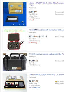
It's more expensive than AA !!!In order to calibrate AA, you must prepare a calibration kit.
Below is the result of searching 'vna calibration kit' on ebay.

Of course, it is good to have such a calibration kit. However, I recommend making a calibration kit inexpensively.
I'll show you a little cheaper.
Below is the result of searching 'calibration kit' on aliexpress. This calibration kit is also good enough.

But as you know, Aliexpress takes time to deliver.
If you have three connectors and 50Ohm resistor, you can make it very easy.
AA requires three calibration tools.
One is open, which means nothing is connected to the connector.
One is short, connecting the center of the connector to the outside.
The other one is short. Connect the center of the connector and the outside with a 50 ohm resistor. (It is the same as the dummy load. It just does not have a cable.)
It is described in detail on the internet site below.
https://www.eevblog.com/forum/rf-microwave/diy-short-open-and-load-for-vna-calibration/
You can make it according to the Connector that is on the AA.
CAUTION: Be sure to format the SD card before updating any other version of the firmware. Alternatively, you can delete only the AA directory in the SD card. The structure of the configuration file differs depending on the type of firmware and may not work normally.
2.Configuration
When you update the firmware, you must first enter the Setup menu.
Click the 'Configuration' button

Click the 'Configuration' Button

If the SD card is formatted or initially set up, it looks like this:

Click the '>' button, change the None -> A
Click the 'Next param >'

ZO : 50, Click the 'Next param >'

OSL_RLOAD, Click the 'Next param >'

OSL_RSHORT : 0, Click the 'Next param >'

OSL_ROPEN : Open, Click the 'Next param >'

OSL_NSCANS : 1 or 3 (I recommend 3), Click the 'Next param >'
(You can increase the value if you want to make more precise calibration, even if the speed is slower.)

MEAS_NSCANS : 1, Click the 'Next param >'
(You can increase the value if you want to make more precise measurements, even if the speed is slower.)

PAN_CENTER_F : Start F, Click the 'Next param >'

LOW POWER TIMER : Off, Click the 'Next param >'

S11_GRAPH_SHOW : Yes, Click the 'Next param >'

S1P FILE TYPE : SMA R50, Click the 'Next param >'

TDR Vf : 66(42h), Click the 'Next param >'

SHOW_HIDDEN : Yes, Click the 'Next param >'

Setup will return to the item for the first time. Continue to click the 'Next param' button.
Since you have set SHOW_HIDDEN above to YES, you will see additional hidden items.
si5351_XTAL_FREQ : 27000000

SI5351_BUS_BASE_ADDR : C0h
(It is the I2C address setting of the Si5351 mounted on the RF board. If AA does not work, set this to Auto Detect and AA will automatically find the I2C address of the Si5351 when it is turned on )

Si5351_CORR : 0
(If I have a chance, I will post a way to find the CORR value easily. If you set the CORR value, you can set a more accurate frequency)

SI5351_MAX_FREQ : 200 ~ 270Mhz
The Si5351 is guaranteed to oscillate up to 200Mhz. However, most Si5351s can generate signals up to 280Mhz.
You can check to see how many Hz the signal can be generated. (Main -> Configuration -> Calibration -> Oscillator Test (FMax))
If you want to use it safely, please select 200Mhz. I recommend 250 ~ 270Mhz.

Si5351_CAPS : 10pF

LIN_ATTENUATION : 6 (06h)

COM_PORT : COM1(ST-Link)

COM_SPEED : 38400

LOW POWER TIMER : Off

BAND_FMIN : 100kHz

BAND_FMAX : 600 ~ 1350Mhz
Enter the number less than the number entered in si5351_MAX_FREQ * 5.
Since the Si5351 is a square wave, there are quite a lot of harmonics. Harmonic is used to measure frequencies higher than 200 MHz.

SCREENSHOT_FORMAT : BMP or PNG

You are back to the initial setup screen.
Click the 'Save and exit' Button

3.HW Calibration
Jumper must be changed to perform H / W calibration. Move the jumper to the HWC as shown below.
Jumper should be located in HWC only when performing H / W calibration, and others should always be in Work.

Click the 'Configuration' button

Click the 'Calibration' Button

Click the 'HW Calibration, only at first run!!!' Button

Click the 'Start HW calibration' Button

If you get a 'No signal' error as soon as you start, check the address of the Si5351, Si5351_MAX_FREQ, and so on. Also check the connection of the wires.


When you see Success, click the Exit button.
(If it has been done 97 ~ 99% and it stopped, SD card is defective. Please format your SD card or try another SD card.)

After all H / W calibration is complete, move the jumper to its Work position.
(Jumper should be located in HWC only when performing H / W calibration, and others should always be in Work.)
4.OSL Calibration
To do this, you need a calibration kit.
Click the 'Configuration' Button in main menu.

Click the 'Calibration' Button

Click the 'OSL Calibration, use calibration kit !!!' Button.

Connect the shorted connector to the S1 port.
In general, there is only one antenna connector, but there is one more antenna port in CEC Modification work, so we will separate each port by S1 and S2.
S1 : The antenna port on the original RF board
S2 : Antenna port added by CEC Modification operation

Click the 'Scan short 0 Ohm' Button

When done, connect the Load (50 Ohm) connector to S1. then Click the 'Scan load 50 Ohm' Button

When done, connect the Open connector to S1. then Click the 'Scan open infinite' Button

When you're done, click the Save and exit button.
Measure SWR for testing.
Click the 'Single Frequency' Button in main menu

Connect 50Ohm Connector or Dummy load to S1 Port.


Example video
This is a video that contains the contents of the above tasks.
5.Calibration for VNA Mode (Tracking scope) - CEC Modification #1
The AA firmware CEC version supports simple VNA mode.
If there is a user who needs VNA function, it will be improved more near VNA, but now only the Scope function with built-in Tracking Generator is provided.
Details will be explained in detail during CEC firmware release.
You do not need any additional devices to use this feature. Only two cables are required.
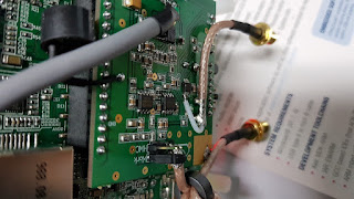
Below is a test cable I made.


Connect the ends of the cables to each other for calibration, The following is a specific circuit, not just two pins connected together. I just used the pin header socket because it was hard to hold it by hand.

You can connect the pins of the cable to each other as shown below.

Click the 'Configuration' button in Main window
Click the 'Calibration' button in Configuration window

Click the 'TX(S2) Calibration for VNA'

Click the 'Start TX calibration' button

When Calibration is finised, 'Success' message appears. click the 'Exit' Button.

Test the calibration for VNA.
Click the 'VNA(S2 -> S1)' Button in Main window.

Click the 'SCAN' Button. The cables must be connected to each other.


If all the frequencies indicate 0dB, the calibration is complete.

Details of this feature will be explained in detail during CEC version firmware release.
Thanks for reading
Ian KD8CEC
When will the CEC version be released?
ReplyDeleteWhere are the HWC and Work pins on my Chinese manufactured Mini1300 model?
ReplyDeleteReading a blog like this makes me happy because we can learn more lessons from this. Window cleaning Bridgewater MA
ReplyDeleteAfter reading this blog i realized we should do antenna in 0 dbm position for better range, as i was doing Research Topics For Digital Marketing I come across to this topic
ReplyDeleteI've expanded my business into hardware, including parts featuring AA Firmware CEC. Leveraging the support of a renowned Storage and Warehousing Services partner worldwide, we ensure efficient logistics. Recognizing the commonality in setup and calibration methods across various firmware, I've streamlined the process for our clients. In response to frequent inquiries, I've meticulously crafted a comprehensive document covering the setup nuances for all products. Now, clients can seamlessly navigate the setup without any hassle, ensuring a smooth and user-friendly experience with our range of products.
ReplyDeleteThis comment has been removed by the author.
ReplyDelete