How to use Nextion LCD #3 - Practice for use with a transceiver
I do not know much about Nextion LCD. During the production of uBITX Firmware which is HF Transceiver, I was introduced by several OMs, The ultimate goal of this article is to create a GUI for the HF Transceiver.
uBITX CEC Version officially supports Nextion LCD from version 1.09.
I will support 2.4 "and 2.8" LCD by default. You do not need to understand everything below to connect uBITX Nextion LCD. Just use the Nextion Editor to load the firmware on the Nextion LCD. If you want to create your own GUI, please read these articles.
How to use Nextion LCD Series
#1 Start Nextion LCD
#2 Programming and application
#3 - Practice for use with a transceiver
#3 - Practice for use with a transceiver
#4 Applied to HF Transceiver
#5 Advanced Application (Applied to various sizes)
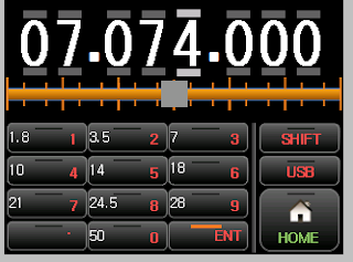
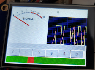
1.About this article
Nextion LCD supports various Controls. A description of the controls required is described in # 1 and # 2.
This document explains how to use the other controls and the actual application through some examples.The examples are necessary for the HF-Transceiver, but anyone can test it because they can test their behavior without a transceiver.
1.S-Meter for transceiver
https://drive.google.com/open?id=1ellTaEwD8QgcitFX0jn-5aX4xuOvBRDW
Execute Netion Editor -> File -> Open Click
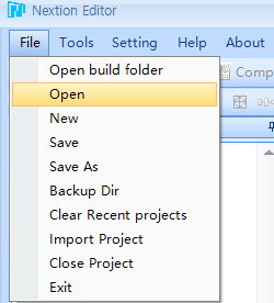
Selected smeter.hmi
It is included in the downloaded compressed file by clicking the link above
You will see the below picture.
this is example for Nextion LCD, However, this may be possible for many applications.
I have implemented code that makes S.Meter behave smoothly.
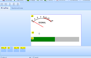
Most of my code is in Timer's Event.
Click the timer Control
You will see the source code
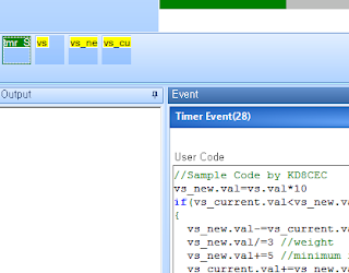
source code
Red is the comment that I add to the source code.
//Sample Code by KD8CEC
vs_new.val=vs.val*10 <-- Nextion LCD is used as a variable using 'Variable' Control.
Nextion LCD provides default variables for sys0, sys1, and sys2.
NOTICE: Do not enter spaces in your code.
if(vs_current.val<vs_new.val) <-- Most are the same as C code.
{
vs_new.val-=vs_current.val
vs_new.val/=3 //weight
vs_new.val+=5 //minimum increase value
vs_current.val+=vs_new.val
vs_new.val=vs.val*10
if(vs_current.val>vs_new.val)
{
vs_current.val=vs.val*10
}
}else if(vs_current.val>vs_new.val)
{
vs_new.val=vs_current.val-vs_new.val
vs_new.val/=7 //weight
vs_new.val+=2 //minimum decrease value
vs_current.val-=vs_new.val
vs_new.val=vs.val*10
if(vs_current.val<vs_new.val)
{
vs_current.val=vs.val*10
}
}
z0.val=vs_current.val+30
n0.val=vs_current.val
j0.val=vs_current.val
//end of source code
Above is a simple code.
How about this?
It is very similar to C language.
The difference is that variable declarations and spaces should not be in your code.
Note: that operations must be performed only once on a line.
Think of it as a simple scripting language. But it is powerful.
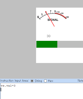
Does it look analog?
You can tweak the source code slightly to adjust the speed up and down.
Let me put up a little more.
type 'vs.val=7' and Enter in command window
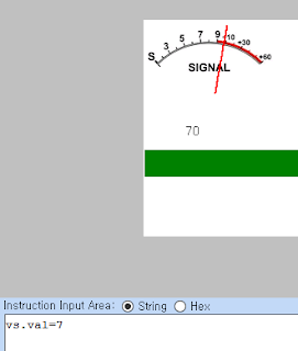
This time, we will reverse the value.
type vs.val=1 and Enter in command window
You can see it slowly go down like an analog meter.
I did not use the Nextion LCD for a long time, I wrote the code referring to the manual on the link below.
https://nextion.itead.cc/resources/documents/instruction-set/
So I'm not sure that the Nextion LCD developer has done what it suggests, But with the simple code above, Nextion LCD did exactly what I wanted.
Now I have written some complicated code. You do not have to understand this. This is just a script.
Below is a test video for this post.
2.S-Meter V2 for transceiver
Download the S-Meter2 file from the link below.
https://drive.google.com/open?id=1KArN_H1I8f4o89pyrG0CpAwZ_S0Vx68j
Did you get used to the S-Meter above?
I made S-Meter a bit more modest with a little bit more
Maybe I can use it when I create a GUI for HF Transceiver.
Since most of the code is the same, only the revision history will be listed below.
- variable name change (vs -> ns, vs_current -> ns_current)
- Using the sys0 Variable
- Add buttons and slides for testing on real LCD
Please watch the video below for changes.
3.Keypad for Frequency Input
Download the Keypad file from the link below.https://drive.google.com/open?id=1sGWCFryTcjAlW8w2b34KUz_PuSigyJ0y
This can also be tested without any additional equipment.
This is a program that uses the touch panel of the LCD to input numbers.
Open 'FreqKeypad.hmi'
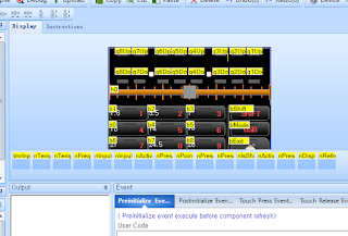
About 70% of the code in this program is in the timer event.
click the timer control,
you will see the source code
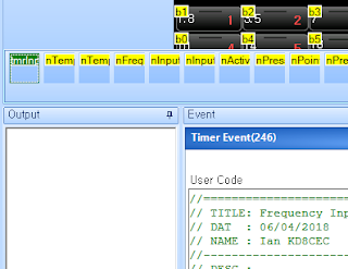
Source code in tmrInput Event
source code
Red is the comment that I add to the source code.
// TITLE: Frequency Input
// DAT : 06/04/2018
// NAME : Ian KD8CEC
//----------------------------------
// DESC :
//==================================
//Check Press Keyvalue
//Check Input Mode (changed InputMode)
if(nInputMode.val!=nActiveInMode.val)
{
nInputFreq.val=0
nActiveInMode.val=nInputMode.val
nPointPos.val=-1
if(nActiveInMode.val==2)
{
nIsShift.val=0
nActiveShift.val=0
bShift.picc=2 <-- Changed Picture in source code
tFreq1.pco=46518 <-- Changed font Color in source code
tFreq2.pco=46518
tFreq3.pco=46518
tFreq4.pco=46518
tFreq5.pco=46518
tFreq6.pco=46518
tFreq7.pco=46518
tFreq8.pco=46518
}else
{
nIsShift.val=0
nActiveShift.val=0
bShift.picc=0 <-- Changed Picture in source code
tFreq1.pco=65535 <-- Changed Font Color in source code
tFreq2.pco=65535
tFreq3.pco=65535
tFreq4.pco=65535
tFreq5.pco=65535
tFreq6.pco=65535
tFreq7.pco=65535
tFreq8.pco=65535
}
}
if(nActiveInMode.val==2)
{
if(nPressKey.val!=-1)
{
//Full Input mode
if(nPointPos.val<1)
{
if(nInputFreq.val<10000000)
{
The operation is done only once per line. such like as assembler
nInputFreq.val = nInputFreq.val * 10 + nPressKey.val <-- (X)
nInputFreq.val*=10
nInputFreq.val+=nPressKey.val
}
nPressIndex.val=1
}else
{
//Full Input mode
//Set value to Fixed Digit
if(nPointPos.val==6)
{
nTemp1.val=nPressKey.val*100000
}else if(nPointPos.val==5)
{
nTemp1.val=nPressKey.val*10000
}else if(nPointPos.val==4)
{
nTemp1.val=nPressKey.val*1000
}else if(nPointPos.val==3)
{
nTemp1.val=nPressKey.val*100
}else if(nPointPos.val==2)
{
nTemp1.val=nPressKey.val*10
}else if(nPointPos.val==1)
{
nTemp1.val=nPressKey.val
}
nInputFreq.val+=nTemp1.val
if(nPointPos.val>=0)
{
nPressIndex.val=nPointPos.val
}
nPointPos.val--
if(nPointPos.val==0)
{
nFreq.val=nInputFreq.val
nInputMode.val=0
}
}
nPressKey.val=-1
nDispFreq.val=-1 //always refress at Key Input
}
nTemp0.val=nInputFreq.val
}else
{
nTemp0.val=nFreq.val
}
//==================================
// Display Digit
//==================================
if(nPressIndex.val!=nPressActive.val)
{
q1Up.picc=0
q2Up.picc=0
q3Up.picc=0
q4Up.picc=0
q5Up.picc=0
q6Up.picc=0
q7Up.picc=0
q8Up.picc=0
q1Down.picc=0
q2Down.picc=0
q3Down.picc=0
q4Down.picc=0
q5Down.picc=0
q6Down.picc=0
q7Down.picc=0
q8Down.picc=0
tFreq1.picc=0
tFreq2.picc=0
tFreq3.picc=0
tFreq4.picc=0
tFreq5.picc=0
tFreq6.picc=0
tFreq7.picc=0
if(nPressIndex.val==1)
{
q1Up.picc=1
q1Down.picc=1
tFreq1.picc=1
}else if(nPressIndex.val==2)
{
q2Up.picc=1
q2Down.picc=1
tFreq2.picc=1
}else if(nPressIndex.val==3)
{
q3Up.picc=1
q3Down.picc=1
tFreq3.picc=1
}else if(nPressIndex.val==4)
{
q4Up.picc=1
q4Down.picc=1
tFreq4.picc=1
}else if(nPressIndex.val==5)
{
q5Up.picc=1
q5Down.picc=1
tFreq5.picc=1
}else if(nPressIndex.val==6)
{
q6Up.picc=1
q6Down.picc=1
tFreq6.picc=1
}else if(nPressIndex.val==7)
{
q7Up.picc=1
q7Down.picc=1
tFreq7.picc=1
}else if(nPressIndex.val==8)
{
q8Up.picc=1
q8Down.picc=1
tFreq8.picc=1
}
nPressActive.val=nPressIndex.val
}
if(nActiveShift.val!=nIsShift.val)
{
nActiveShift.val=nIsShift.val
//Shift Mode Toggle
if(nActiveShift.val==1)
{
bShift.picc=1
b1.picc=1
b2.picc=1
b3.picc=1
b4.picc=1
b5.picc=1
b6.picc=1
b7.picc=1
b8.picc=1
b9.picc=1
b0.picc=1
}else
{
bShift.picc=0
b1.picc=0
b2.picc=0
b3.picc=0
b4.picc=0
b5.picc=0
b6.picc=0
b7.picc=0
b8.picc=0
b9.picc=0
b0.picc=0
}
}
//=================================
// DISPLAY Frequency
//=================================
if(nDispFreq.val!=nTemp0.val)
{
nRefreshCount.val=0
}else
{
nRefreshCount.val++
}
This part is used to cut the frequency string one by one.
if(nRefreshCount.val<3)
{
nDispFreq.val=nTemp0.val
//digit 1
nTemp1.val=nTemp0.val%10
cov nTemp1.val,tFreq1.txt,1
//digit 2
nTemp0.val/=10
nTemp1.val=nTemp0.val%10
cov nTemp1.val,tFreq2.txt,1
//digit 3
nTemp0.val/=10
nTemp1.val=nTemp0.val%10
cov nTemp1.val,tFreq3.txt,1
//digit 4
nTemp0.val/=10
nTemp1.val=nTemp0.val%10
cov nTemp1.val,tFreq4.txt,1
//digit 5
nTemp0.val/=10
nTemp1.val=nTemp0.val%10
cov nTemp1.val,tFreq5.txt,1
//digit 6
nTemp0.val/=10
nTemp1.val=nTemp0.val%10
cov nTemp1.val,tFreq6.txt,1
//digit 7
nTemp0.val/=10
nTemp1.val=nTemp0.val%10
cov nTemp1.val,tFreq7.txt,1
//digit 8
nTemp0.val/=10
nTemp1.val=nTemp0.val%10
cov nTemp1.val,tFreq8.txt,1
}
Click the 'bShift' button control
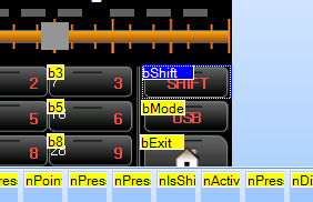
You will see the flow source codes
This is an example of the button behaving differently depending on the current state.
When the Shift Button is pressed, nIsShift.val is filled with a value of 0 or 1.
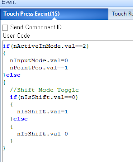
Click the number button ('b1' control) this time.
You can see that it behaves differently depending on the value of nIsShift.val
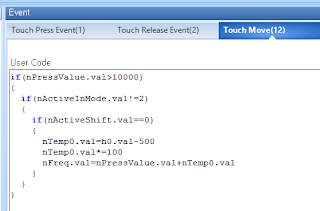
Finally, click the Slider control.

The following three pictures are Slider control events.
This is the action when touching the slide control.
This is the action when the slider control is moved to the left or right.
(Adjusts the frequency by moving the slider)
4.Execute Keypad Example
Click the 'debug' button
It will be displayed on the screen as shown below.
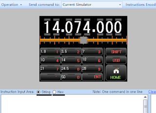
Press 7 on the Key Pad.
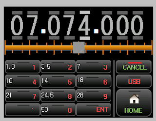
Frequency Indicates that the color has been switched to the current frequency input state as Gray.
Then press '.'
Maybe '7' would have moved to Mhz.
This is a way to quickly enter frequencies.
Then type '0', '7', '4' in order.
It will appear as shown below.
When you want to confirm this, press the 'ENT' button.
The frequency have changed to white as shown below.
This means the current frequency has been changed to 7.074.000 Mhz.

This time, I will raise the 100Hz unit directly.
Touch the top of the 100Hz position.
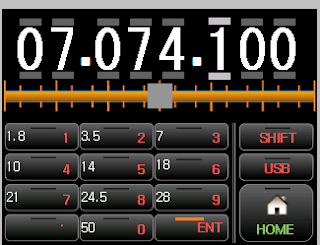
You can adjust the frequency directly as above.
Did you notice?
Yes, that's right. I imitated the cool program Ham Radio Deluxe.
Move the slider below to the left or right.
Does the frequency change drastically? This is what I intended.
By using these two you can easily set the frequency you want.
Did you notice it again?
Yes. This also brought the motif from Ham radio deluxe.
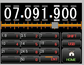
press the Shift button.
The color of the Shift Button has changed and the color of the Keypad has changed.
Please press '21' in this state.
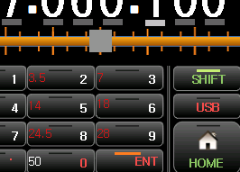
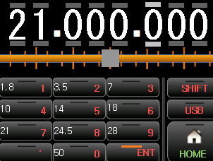
Has the frequency changed to 21Mhz?
I am thinking about replacing this part with the center frequency of the Ham Band.
You can modify the button event to get the action you want.
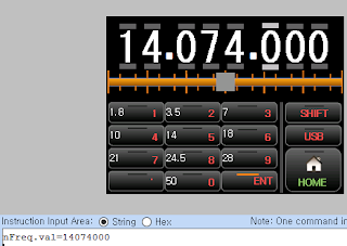
Let's enter the frequency in the command window.
type nFreq.val=14074000 and Enter in command window
You can see that the frequency changes immediately.
Below is a test video for this post.
I will finish the article on Nextion LCD.
In the following article, we will explain how to apply Nextion LCD to uBITX(HF transceiver)
Thank you for reading the long article.
Ian KD8CEC
In the following article, we will explain how to apply Nextion LCD to uBITX(HF transceiver)
Thank you for reading the long article.
Ian KD8CEC


Thanks for hard work on developing these articles
ReplyDeleteVe1bwv
Thank you joe
DeleteGreat job and clear explanation, thanks!
ReplyDelete73 de PD0DIB
Excellent and hard work Ian, congratulations and thank you for share it with us !
ReplyDeleteI made also some app for Nextion and transceivers,this is a great display and work with him for 2 years now; but I'm not a programmer and on complex stuff I am stuck..
for example, I made an external CAT control for my Icom 7000, but I cannot extract useful part from CAT to display frequency on Nextion, especially because all data it is on a single wire not on two, like on Yaesu for example; can you help me a little with that when you have a little time?
Thank you in advance, my best 73 !